- Steam traps
- Pressure regulators
- Control valves
-
- Control valves
- Two-way control valves
- Three-way control valves
- two-way on/off globe valves
- Intermittent blowdown valves & TDS blowdown control valves
- Pneumatic and electric linear actuators
- Universal controllers, transmitters, temperature sensors, digital panel, pneumatic and electric positioners
- Self-acting temperature control valves
- Two-way overflow valves
- Boiler house and special equipment
-
- Boiler house and special equipment
- Separators steam and compressed air
- Shell and tube & plate heat exchangers
- Sample coolers
- Direct steam injectors
- Flash vessels with inbuilt steam trap
- Blowdown expansion and cooling units in boiler houses
- Exhaust heads
- Hot condensate coolers
- Condensate lifting pots
- Steam-water mixers & Water-saving guns
- Level gauges & Magnetic level indicators
- Pressure operated pumps and packaged pump units
- Pipeline ancillaries
- Packaged units / Skids
- Clean steam equipment
-
- Clean steam equipment
- Clean Steam Generator
- Thermostatic clean steam traps
- Clean Service Control Valves
- Sanitary pressure regulators
- Clean Steam Separators
- Culinary steam filters
- Hygienic steam filters
- Clean Service Safety Valves
- Hygienic vacuum breakers
- Sample cooler clean steam
- Clean steam injectors
- Direct steam injection humidifiers
- Mushroom style air vent
- Three piece hygienic ball valves
- Three piece high purity ball valves
- Sanitary sight glass
- Sanitary pressure gauges
- Sanitary air vent valves
Thermal deaerator PRIMA-STEAM DASP
Specifications
Documentation
Under the order
Dimensions
відповідно до конкретних вимог установки
Deaeration is the final stage of feedwater treatment and plays a crucial role in preventing corrosion of thermal power equipment and pipelines. Thermal deaeration is the most effective and versatile method of removing all dissolved gases from water, which is widely used in the thermal power industry. The essence of thermal deaeration is to create conditions for dissolved gases to escape from water into the vapor-gas space of the deaerator and then be released into the atmosphere. The method is based on overheating of water above the boiling point, which corresponds to the pressure in the working area of the deaerator.
Water at a temperature of 102-104°C for atmospheric deaeration is fed into the deaerator, where it is crushed and the deaerated flow rate is increased several times. The deaerated stream is then fed to the cylindrical working surface of the deaerator, where the vapor-gas and water phases are separated by gravitational and dynamic forces. The deaerated water is fed to the feed (make-up) pump or to a storage tank (deaeration tank), and the vapor-gas mixture is discharged from the deaerator through the deaerator vapor outlet to the vapor cooler (heat exchanger) or to the atmosphere.
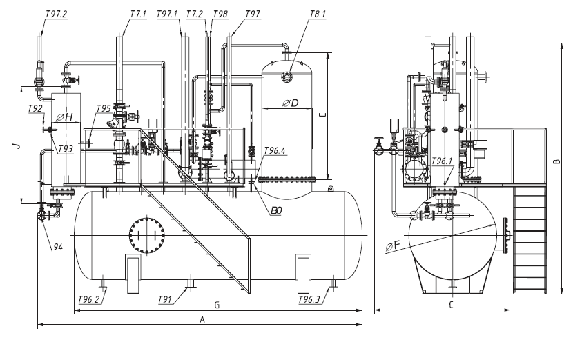
Dimensions of the deaeration unit of the DASP series
|
DASP |
А-2 |
А-4 |
А-6 |
А-8 |
А-10 |
А-12 |
А-16 |
А-20 |
А-24 |
А-30 |
А-40 |
А-50 |
|
|
A |
mm. |
2365 |
4735 |
4735 |
5915 |
5915 |
|||||||
|
B |
mm. |
3200 |
3210 |
3310 |
4050 |
4070 |
4125 |
4470 |
4560 |
4645 |
5475 |
5535 |
5595 |
|
C |
mm. |
1240 |
1240 |
2050 |
2250 |
2650 |
|||||||
|
D |
mm. |
320 |
420 |
520 |
610 |
710 |
710 |
910 |
910 |
1112 |
1212 |
1312 |
1412 |
|
E |
mm. |
1750 |
1760 |
1860 |
2000 |
2020 |
2075 |
2220 |
2310 |
2395 |
2825 |
2885 |
2945 |
|
F |
mm. |
800 |
1200 |
1200 |
1600 |
2000 |
|||||||
|
G |
mm. |
2100 |
4200 |
4200 |
5250 |
5250 |
|||||||
|
H |
mm. |
528 |
630 |
630 |
|||||||||
|
J |
mm. |
2140 |
|||||||||||
|
K |
mm. |
620 |
720 |
820 |
950 |
1050 |
1050 |
1216 |
1216 |
1416 |
1632 |
1742 |
1832 |
Configuration of technological and auxiliary equipment of the DASP series deaeration unit
BASIC :
К1 - Deaeration column - 1 pc.
К2 - Deaerated water tank - 1 pc.
- Safety device for protection against exceeding the permissible overpressure - 1 pc.
- Safety device for protection against exceeding the permissible vacuum - 1 pc.
- Safety device for protection against exceeding the permissible water level in the tank – 1 pc.
- Automatic steam pressure control unit in the deaerator - 1 pc.
- Automatic water temperature control unit in the deaerator - 1 pc.
- Unit for automatic maintenance of the level of veda in the deaerated water tank - 1 pc.
- Equipment for automatic control and indication of deaerator performance indicators.
КЗ - Control panel - Automatic control panel of the deaerator, based on an industrial controller. Complete with sensors.
ADDITIONAL :
К4 - Vapor cooler - 1 pc.
К5 - Separator of continuous blowing with utilizer - 1 pc.
– Thermal insulation
- Service platform
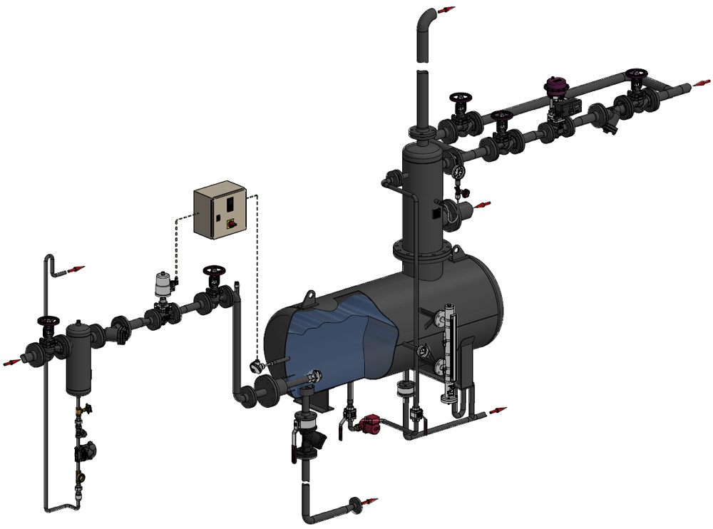
Thermal diagram of the deaeration unit of the DASP series

|
|
1. Deaeration column - 1 pc.
• Safety device for protection against
|
• Equipment for automatic control
|
Purpose and sizes of nozzles of the deaeration unit of the DASP series
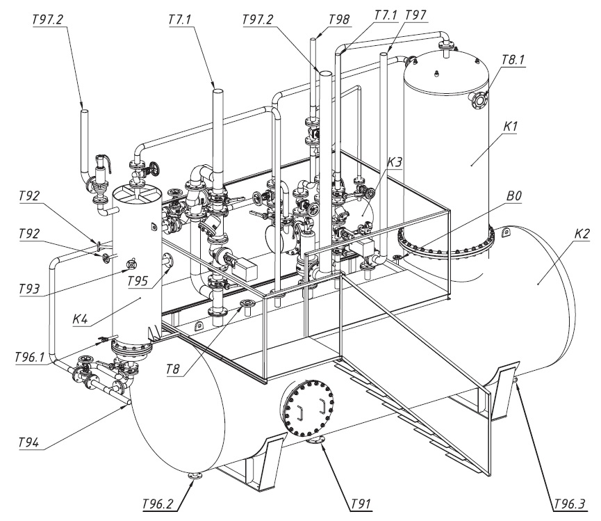
| Type of deaerator | DASP | ||||||||||||
| А-2 | А-4 | А-6 | А-8 | А-10 | А-12 | А-16 | А-20 | А-24 | А-30 | А-40 | А-50 | ||
| Nipple | Purpose of the nozzle | Nominal diameter of the nozzle (DN), mm. | |||||||||||
| Т7.1 | Decontamination steam nozzle | 50 | 80 | 100 | 125 | 150 | |||||||
| Т7.2 | Steam supply pipe for bubbling | 15 | 25 | 40 | 50 | 80 | |||||||
| T8 | Superheated condensate nozzle | 25 | 25 | 50 | 65 | 100 | |||||||
| Т8.1 | Cooled condensate nozzle | 25 | 40 | 50 | 80 | 100 | |||||||
| Т91 | Feed water outlet | 40 | 65 | 100 | 125 | 150 | |||||||
| Т92 | Continuous purge nozzle | 20 | 25 | ||||||||||
| Т93 | Periodic purge nozzle | 20 | 25 | ||||||||||
| Т94 | Softened water connection | 25 | 40 | 50 | 80 | 100 | |||||||
| Т95 | Chilled purge water outlet | 50 | |||||||||||
| Т96.1 | Purge water discharge nozzle 1 to the drain | 20 | |||||||||||
| Т96.2 | Deaerated water overflow nozzle | 25 | 40 | 50 | 80 | 100 | |||||||
| Т96.3 | Deaerated water drain pipe | 50 | |||||||||||
| Т97 |
Spigot to prevent excessive vacuum |
65 | |||||||||||
| Т97.1 | Pipe of the breaker valve | 40 | 50 | 100 | 100 | 125 | |||||||
| Т97.2 | Separator Valve Pipe | 50 | |||||||||||
| Т98 | Vapor extraction nozzle | 15 | 20 | 20 | 40 | 80 | |||||||

